FreeCAD is a 3D parametric modeling program designed for creating and customizing real-life objects. It’s completely free and open-source.
FreeCAD is organized in Workbenches, which provide different layouts of tools depending on the task at hand. This means you can do a lot with the same program, such as drafting, modeling, or assembling.
In this tutorial, we’ll model a simple storage chest, which can be 3D printed later on or left as a model. We’ll go over how the program is organized, how to use each of the necessary tools, as well as some advice in case you want to take the next step and 3D print it.
Contents
Step 1: Setting Up
Downloading FreeCAD is very simple, you don’t need to register or take many steps. Simply go to the download page of the FreeCAD site and click the download button. FreeCAD works for Linux, MacOS, and Windows, so select your OS accordingly.
Once the program is downloaded, there are a few things to set up and familiarize yourself with before starting a new design.
Navigation Style
In FreeCAD, you can set the navigation style in a few different ways, with setups that resemble other programs in terms of hotkeys and the layout.
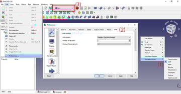
To set the navigation style, right-click anywhere on the workspace and go to “Navigation Style” (#1 in the image above). There, you’ll see many options. As we’ll be creating a model using CAD, the best option is to leave it as such.
Units
Units affect your project when you use dimensions and also when drawing, and they ultimately depend on the project you’re doing (or your personal preference).
To check the units, go to Edit, on the top menu, then “Preferences > General > Units” (2). In this case, we’ll use the metric system in mm, and if you’re modeling to 3D print, we recommend you do the same, as slicing programs usually work in the same system.
Workbenches
Finally, as we mentioned, FreeCAD is organized in Workbenches. As we’ll be modeling, we’ll be switching between the “Part Design” workbench and the “Part” workbench.
To switch workbenches, go to the workbench menu at the top of the toolbar (3). When you switch workbenches, you’ll see the tools in the toolbar change.
It’s also possible to customize the position of the tools by dragging and dropping them. We recommend moving them so that you can see all tools at the same time, as some will be stacked to the right of the screen and hidden.
Step 2: Sketching a Base
We’ll start by modeling the bottom part of the chest. For our example, we’ll give you all the measurements, but if you’re creating something of your own that you plan to print, take care that the dimensions you set at this point will fit on your printer’s build plate.
To model the bottom of the chest, we’ll essentially model a hollow box without a lid (the lid comes later). To start, go to the “Part Design” workbench, where we find the sketching tools.
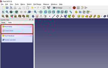
- To sketch a base, under the Combo View box to the left of the Viewport, go to the Tasks tab and you’ll see the option to create a body.
- Click “Create sketch”, and FreeCAD will ask you to select a plane in which you want to design your model. Although this is a 3D model and you can rotate it around, it’s good practice to choose the plane according to how you’re going to design the part.
- We’ll select the XY-plane, which is viewed from above, as we’ll be drawing the bottom part of the chest. Select this plane and press “OK”.
Sketching Tools
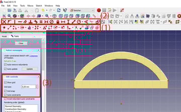
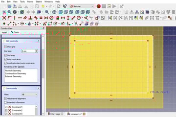
As FreeCAD is parametric modeling software, you sketch by using drawing tools (1) and constraint tools (2). To make sketching easier, you can enable the grid (3).
- To show the grid, go to the Combo View in the Tasks tab.
- There, there’s a drop-down menu called “Edit Controls” where you can choose to show the grid, change its size, and activate grid snapping.
- In this case, we’ll set the grid spacing to 5 mm, as we’ll be working with around 100 mm on each side, so 5 mm is a good incremental space. If you’re designing a smaller model, you might prefer to choose smaller increments (e.g. a 10 x 10 mm model would work well with 1 mm spacing).
Drawing the Sketch
To sketch the chest bottom, we’ll start by drawing a base rectangle.
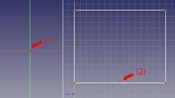
- The red dot on the center of the screen (1) is the origin point, so coordinate systems in reference to the origin point work from there.
- We’ll draw an 80 x 60 mm rectangle parting from the origin. You can see the coordinates as you move, which will help you draw.
- When you’re done, you’ll see small straight red lines inside the rectangle edges (2). These are constraint lines and they indicate the lines are horizontal and vertical.
- The sketch is done for now, so we can close it.
Step 3: Extruding a Boss
For now, the rectangle we have is a 2D shape, and we need to give it some height so it becomes a 3D shape and can form the base of our box.
- With the sketch closed, go to the Combo View in the Model tab, and you’ll see there’s now a sketch on the hierarchy tree. Select the sketch by clicking on it once. (To edit an existing sketch, double click it and you’ll go back into sketch mode.)
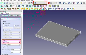
- Go to the Part workbench. Here, you have the option to “Extrude from a selected sketch” (1).
- In the Tasks tab, you can then set properties including the length of the extrusion, which we’ll set to 5 mm.
- Press OK. This will apply the changes and take you out of extrusion mode.
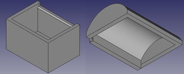
Step 4: Creating the Hollow Box
Now that we’re working in 3D, we can convert our flat model into a hollow box shape.
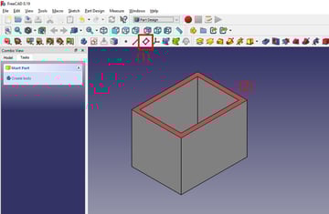
- To create the walls of the chest, go back to “Part Design”, select the body, and in the Tasks tab create a new sketch.
- In this sketch, we’ll create two rectangles. One that’s the same size as the first rectangle, and a second rectangle that fits 5 mm inside the first one. This means that the walls of the chest will have a thickness of 5 mm.
- Select this sketch, go back to “Part”, and extrude the base to a length of 60 mm by repeating the instructions in step 3, above.
If you’re designing your own model to 3D print, be careful about the wall thickness you choose at this stage. Walls that are too thin may not even be printable or could end up too brittle for practical use. Also be aware that the height you extrude to shouldn’t exceed the build volume of your printer.
Unifying Solids
At this stage, the bottom and the walls look like separate shapes because (from the perspective of the software) they’re still different bodies. This won’t necessarily affect the printability of a part, but when modeling, it can have important implications. To fix this, FreeCAD has to go a bit of the longer route as there isn’t an option to directly create features inside the same body.
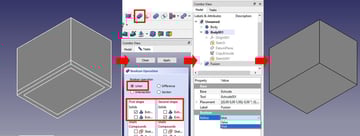
- Select the two bodies on the model tree, and from the Boolean operations select “Union”. Now they will be the same part and it won’t look as if they overlap, but you may still see the separate lines as if they were two bodies.
- To make those lines disappear, select the Fusion element in the Model tree, which is our combined model. In the properties, change the Refine option to “true”. Now the program shows and interprets it as one combined shape.
Step 5: Adding a Lid Slot
Now we need to make the slot where the cover will fit. For this, we’ll be modifying the top of the model, so we need to create a new reference plane in that area.
Creating New Reference Geometries
In FreeCAD, reference planes are called “Datum planes” (1) and you can find them in the Part Design workbench.
- Select the top face (2) and set it as a datum plane. In this case, we don’t need any more references, so don’t select anything else.
- Set all offsets to zero, so the datum plane is touching the top face.
Extruding a Cut
To cut into a body in FreeCAD, you extrude a shape and then use Boolean operations to subtract that shape from another body.
- Select the first body, go to Tasks, and create a new sketch. When FreeCAD asks you to select a plane, select the newly created datum plane.
- We want to make a slot for the lid of the chest, so draw a rectangle on the datum plane along one of the long walls, leaving 5 mm at each end.
- Go to the “Part” workbench and extrude the new rectangle 5 mm down. At this point, we’ll have two shapes, our chest base, and the rectangular prism on top.
- Select both bodies and use the Boolean operation “Difference” to subtract the rectangular prism from the chest.
- On the “Cut” feature that appears on the model tree, make sure “Refine” is set to true.
Step 7: Creating the Cover
To create the cover, we’ll create a new part.
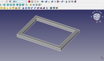
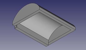
- Using what we’ve learned so far, create a hollow rectangle on the XY-plane and extrude it to be 5 mm high. The outside rectangle will be 80 x 60 mm and the inside will be 70 x 50 mm (5 mm smaller in all directions) to match the chest. You can see the result in the image above.
- Select one of the shorter side faces and create a new datum plane there.
Using Constraints
We’re now going to create a circle to give the cover a round shape. The steps described at this stage can be seen completed in the image above, so you know what you’re aiming for.
- Select the midpoint 10 mm below the bottom of the solid (30 mm from each side) and make a circle of any radius.
- Add a point in the top right corner of the rectangle. We’ll use a constraint that fixes a point to an object. This will make the radius of the circle be coincident, which makes it snap to the corner of the rectangle.
- Create a second circle from the same point to give thickness to the cover.
- Add another point inside the cover, touch the inside wall, and use a constraint to make the second circle snap to this point.
Trimming
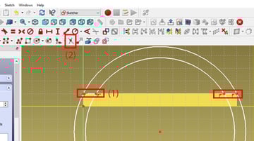
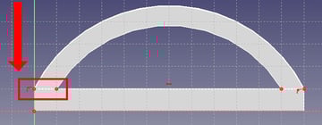
- To limit the extension of the circle, as we only need a portion of it, we’ll simply draw lines where the circle needs to stop (1). As seen above, this corresponds to the bottom and left-hand edges of the visible rectangle.
- To trim the rest of the circle we’ll use the trim tool (2).
Extruding the Cover
Before doing anything else, copy and paste the sketch, as this will save us time in the long run.
- Extrude the curved sketch until it reaches the other side of the model (80 mm).
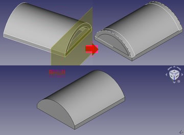
- Now, with the copy of the sketch, we’re going to make some slight modifications. Delete the inside part of the drawing, leaving only the outside.
- Draw a line to complete the bottom of the base. That way, this part has a solid shape instead of a hollow one. The resulting sketch is shown in the image above.
- We’re going to extrude this 5 mm, and we’re going to repeat the same on the other side by creating a new datum plane. This makes up the side walls of the cover.
- With all parts done, fuse the results using Boolean operations to complete the lid.
Step 8: Adding Details to the Cover
We now repeat the instructions of step 5 but for the cover. This time, we’ll extrude the rectangle by 3 mm, but instead of cutting it away, we’ll combine it to make it a part of the same body.
The second detail we’ll add is to create the cylinders that are going to snap-fit to the circles created in step 5. These circles sit on either end of the rectangular prism attached to the cover, and should have a diameter of 2 mm and a length of 1 mm. Remember to use the Boolean operation to combine, instead of cutting, as we want these cylinders to stick out from the cover.
At this stage, it’s a good moment to add some explanations about these dimensions and how they’re affected by the 3D printing process.
The cylinders attached to the cover are smaller both in diameter and length than the holes in the box, to account for the printer’s tolerance and to allow the parts to move. If the extruded and cut-away parts were designed to the same dimensions, they would be unlikely to snap together and would be difficult to move and use.
The results of your print ultimately depend on your slicer settings, but a common setting to use is a 0.2 mm layer height. With this setting, it will take five lines of filament to reach the length of 1 mm. Any fewer lines of filament might not stand up to the wear of attaching and using the cover. On the other hand, the length is set to 1 mm because the tight fit means anything longer might break as you try to snap it into place.
Advice & Considerations
With our model done, let’s talk about some additional aspects about FreeCAD and how to 3D print a model.
When you save a project, it is stored by default as a FreeCAD Document. If you want to save it for other uses, including 3D printing, you have to export the file. In this case, you also need to select which bodies within the file to export.
When exporting, you have many files options. Here’s a rundown of the most useful ones:
- OBJ and STL formats are useful if you want to 3D print or take into artistic modeling software to add detail.
- STEP and IGES formats are useful to keep information about specific software features used and are compatible with other modeling software, like SolidWorks and Fusion 360.
When you’re designing, it’s important to also plan for the manufacturing process your part will go through, meaning you have to take into account if certain geometries are actually possible to make.
Additionally, if you’re planning to 3D print your model, there are some special considerations to take. As we mentioned, things like wall thickness and your printer’s build volume are important to keep in mind if you’re designing a part to be a certain size.
For things like the snap-fit knobs used to assemble this box, you also have to take into account your printer’s tolerance either when modeling or when scaling it to print, to make sure it will fit together in reality.